picspalsandgals
University of Washington Electrical Engineering Blog
Radio time!
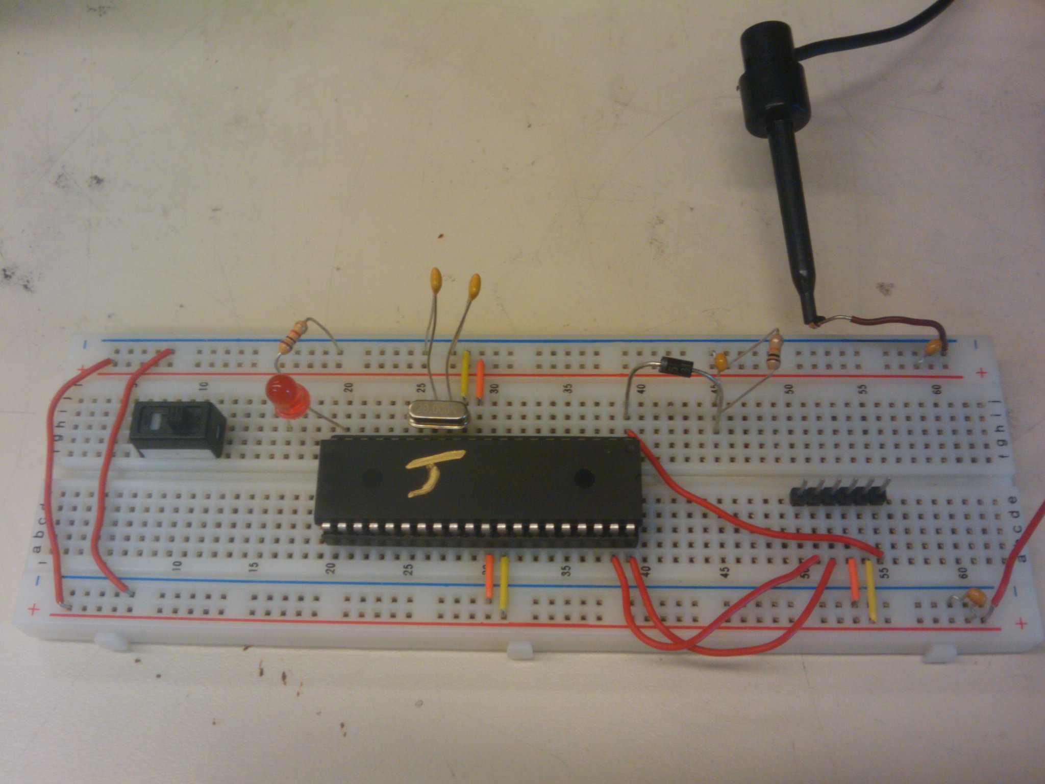
The last two posts were really just getting up to speed on how the MSP is coded. Now its time to get it to do something interesting! We’re going to use the MSP’s radio to control the onboard LED. This application is loaded on to two separate MSPs and once they’re powered up pressing the button on one of the MSPs will toggle its own red LED and the other’s green LED. Let’s take a look at the code.
#include “mrfi.h”
int main(void)
{
BSP_Init(); //Disable WD, Set MCLK to 8MHz, set LED to out, and BTN to inttrupt
P2DIR |= 0x08; //Set Pin six as out
P1REN |= 0x04; //Enable BTN resistor
P1IE |= 0x04; //Enable interrupts on button press
MRFI_Init(); //Enable radio
MRFI_WakeUp(); //Power up radio, connect 26Mhz Oscilator
MRFI_RxOn(); //Enter Rx mode
__bis_SR_register(GIE+LPM4_bits); //Enable global interrupts and enter low power mode 4
}
void MRFI_RxCompleteISR() //
{
P1OUT ^= 0x02; //Toggle Recivers Green LED
}
#pragma vector=PORT1_VECTOR //Declaration of function to call on interrupt
__interrupt void Port_1 (void)
{
P1IFG &= ~0x04; //Dismiss interrupt flag
P1OUT ^= 0x01; //Togle Sender Red LED
mrfiPacket_t packet; //Create a message packet
packet.frame[0]=8+20;
MRFI_Transmit(&packet, MRFI_TX_TYPE_FORCED);
}
Again the code is pretty messy, so I’ve done my best to comment it. In main we see the same code as previously discussed to enable the LEDs, pull up resistors, and interrupts. We also see some new stuff like the BSP and MRFI commands. These are just start up methods to set up the radio. The important sections here are the “__interrupt void Port_1 (void)” and the “void MRFI_RxCompleteISR()”. The Port_1(void) method is run every time we get an interrupt from a button press. This method first dismisses the interrupt flag and toggles the green LED on board. Next it puts together a bunch of packet information and transmits it to the paired MSP. This is where the RxCompleteISR() method comes in. When ever an MSP receives a packet this method is called, and in this case toggles the green LED.
The thing that I really like about this code is the symmetry. The exact same code is loaded on to two separate MSPs, and the interrupts deal with making sure the correct action happens on each board.
In the last post we managed to toggle the MSP’s LEDs using a power hungry active waiting loop. This time let’s try to do it with interrupts instead. The MSP has a low power clock called the ACLK. We’re going to use it to count to a value, then trigger an interrupt that toggles the LED state. This application is a little less clear than the previous one due to the cryptic register names, so I’ve done my best to comment it clearly.
#include “io430.h”
#include “in430.h”
int main( void )
{
WDTCTL = WDTPW + WDTHOLD; //Set up the watch dog timer
P1DIR |= 0x03; //Set the LED’s to output
BCSCTL3 |= LFXT1S_2; //Set the ACLK to a low power oscillator
TACCTL0 = CCIE; //Enable Interrupts on timer_A
TACCR0 = 1000; //Set the value the timer counts up to
TACTL = MC_1+TASSEL_1; //Tell timer_A to increment each time ACLK ticks
__bis_SR_register(GIE+LPM3_bits); //Enable Global Interrupts, and go into Low pwoer mode
}
#pragma vector=TIMERA0_VECTOR //Set the interrupt to trigger the following function
__interrupt void Timer_A (void)
{
P1OUT ^= 0x03; //toggle the LEDs (Finally!)
}
The code seems a little scary to look at, but it comes down to a fairly basic plan: have a counter (timer_A) increment each time a clock (ACLK) ticks, then once it counts to 1000 toggle the LEDs.
Now admittedly, there are a couple things I haven’t figured out about this program, and am going to have to look into further. First, embedded applications usually have a while (1) loop that contains their main processing, but that’s not the case for this program. This would imply that the program executes once then resets. But, if this is the case how does the timer keep track of what its currently counted to? My guess is that since there is only a soft reboot (the power doesn’t cycle), there is a low level register that keeps track of the timer regardless of the high level application running. My second question is with the interrupt syntax. After spending a significant amount of time looking over this code snippet, I can’t tell what exactly the “#pragma vector=TIMERA0_VECTOR” line does. It appears that it sets a variable “vector” to a specific value, but what exactly that does to connect the interrupt to the specified function is a mystery. Hopefully more playing with the code will reveal what going on.
I mentioned that this version of the blink code should be more efficient power wise. We connected a 1 ohm resistor in series with our supply to approximate the current drawn by the MSP. When running the version of the blink code from last time (with the active for loop) we measured a current draw of 2.2 mA, while the timer interrupt version required only 1.7 mA. This seems like a small change, but in the world of embedded systems a draw of .5mA can make or break a system. Note that this is a difference between low power modes zero and four. We initially heard that the MSP has closer to twenty different low power modes, but so far we have only been able to gain access to LPM0 through LPM4
Next on the list is configuring and using the MSP’s radio to start communicating between devices!
Diving into the MSP 430
We recently started working the MSP 430 RF2500. It’s the basic MSP 430 processor, with the addition of a CC2500 Radio. It’s programed in C with access to low level registers and hardware. Thomas Watteyne, a professor at Berkley, has produced a great walk through for this device, and we have been slowly working through the different tutorials he presented, and I want to take a minute to talk about the first of three of the basic projects we’ve mastered so far. The code for each project is included below, and in the code section of our page.
#include “io430.h”
#include “in430.h”
int main( void )
{
WDTCTL = WDTPW + WDTHOLD;
int i;
P1DIR |= 0x03; //Set LED’s to Output
while (1) {
P1OUT ^= 0x03; //Toggle LED state
for (i=0;i<10000;i++) {
__no_operation();
}
}
}
First is a basic blink program. This application will toggle one of the on board LED’s, and while it’s very inefficient power wise it shows some of the basics for working with an MSP. The two important commands here are P1DIR and P1OUT. P1 refers to port 1 of the 4 available on the MPS, each with 8 pins of IO. DIR sets a port to either input or output based on a binary value. OUT sets the pins on a port to logic high or low, also based on a binary value.
From the MSP data sheet we can find that the on board LED’s are connected to pins 0 and 1 on port 1, so the binary to address them is 00000011. This translates to 0x03 in decimal, as used in the code above. The address is then bit-wise OR’d with the P1DIR to set the LED’s to outputs. To blink the LED the address is bit-wise XOR’d with P1OUT to toggle the on off state, and then followed by a for loop delay. This is then wrapped in the while(1) loop standard to most embedded applications.
I mentioned above that this is a really power hungry application. The problem is with the no_operation command. This basically burns an entire clock cycle to do nothing. Although a single no op seems trivial, notice that its wrapped in a for loop that runs 10,000 times before we actually toggle the LED’s. The solution turns out to be to use interrupts, which we’ll go into in the next post. Stay tuned…
Weekly Update: Visual(Thursday)
So maybe not weekly. Its been awhile since we have posted here. Been a pretty crazy quarter so far however we have peen making some progress. Right now we are working on creating a PIC USB device that can configured to send any data to the computer. This has proved to be a complex procedure. I was able to get Visual Studio from the UW website and have begun to figure out how to write basic .exe programs. By taking apart the WFF code we have begun to dissect the basic setup for the windows application. We will update when we get communication.
PIC 18F Hello World with LCD!
This is just a quick post to give an idea of how easy hello world with an LCD can be done. The main.c code file will be posted in the code section as well. This demo (see picture below) uses a PIC18F4455 with a standard 16×2 LCD to display text. The crystal oscillator used is a 20 MHz crystal and other than that, the rest of the circuit is fairly trivial: give it power, hook up the oscillator and attach the 8 data pins for the LCD to PORT D on the PIC in the same numerical order (RD0->D0, etc) and the R/S, R/W and E lines for the LCD are attached to PORT C. The code was compiled using Hi-Tech PIC C18 and the LCD code is fairly generic code that was included with PIC C. If we get time, a schematic will be posted as well.
Here is the circuit in action:

PIC18F4455 Hello World LCD
And here is the schematic (this has a temperature sensor on it as well…see next post for how to use that!):

PIC18F4455 LCD and Temperature Sensor
Hello World in C


USB!
And that is a USB win! We have accomplished computer controlled LED blinking. We are going to have to find a camera for video, but by following the USB tutorial on the links page we were able to turn a LED on and off with a click of a mouse. It was extremely cool. Next step is to flush out the example program to control more pins and take input from other sensors.
USB Tutorial
We are now working on the USB tutorial for the 18F4550. This is proving to be much more difficult than the blinking LED. Our main problem is the C compiler for Mplab. However here is the schematic that we are following. It was obtained the from website linked to in the links section: USB tutorial.

Also, here is the female USB-Type B wiring diagram.

Platforms
These are the three platforms we will be using(linked to mouser).
Jumping into PIC’s

Here is the setup for our basic foray into PIC’s. We found this project on a tutorial page for 18F PIC’s called http://www.pic18f.com. All of these tutorials are based on the 18F4550. Since we are using the PicKit3 programmer here is the pin out.

